Arrow Diagramming and Precedence Diagramming
Critical Path Method – ADM and PDM
Different techniques are being used to represent the project graphically, mainly to represent project activities, resources and objectives and network diagrams provide a basis for planning. Network diagrams are used to identify the critical path and also project completion time.
Network diagrams reveal inter-dependency of activities, help schedule resources and also help understand project start and end dates. There are different techniques for network scheduling and ADM and PDM are two among them. ADM stands for Arrow Diagramming Method and PDM stands for Precedence Diagramming Method. You can perform Critical Path Method (CPM) analysis for arrow diagrams and precedence diagrams.
Arrow Diagramming Method
Arrow Diagram is also known as Activity on Arrow diagram. As the name indicates, activities are represented on arrows in this method. The length of the arrow is not at all relevant. The description is written on the shaft of the arrow. The arrow tail represents the start of activity and the arrow head represents the end of the activity. Precedence relationships between activities are represented by circles connected by one or more arrows. Each activity should have a definite beginning and end represented by nodes.
![]()
Arrow diagram can show an activity with duration of zero. These activities are known as dummy activities and are usually represented using dashed lines. Dummy activities represent dependencies between tasks. In the above diagram, the activity B-D is a dummy activity.
Precedence Diagramming Method
Precedence diagram is also known as Activity on Node diagram and as the name indicates activities are represented on nodes in this method. Boxes are referred to as nodes. The description is written in a box and lines connecting boxes have arrow heads showing the direction. Precedence diagrams cannot represent dummy activities with duration of zero. Arrow diagrams are widely used and more popular compared to precedence diagram.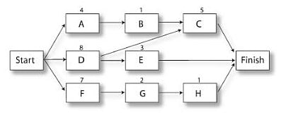
In both arrow diagrams and precedence diagrams, networks flow from left to right. Each activity is identified with a unique number and an activity cannot start until all of its preceding activities are complete. For example, as per the activity on node diagram shown above, the activity C cannot start until activities B and D are complete. The number representing an activity should be greater than its predecessors. The start and stop nodes should be unique.
Network Diagrams
Mainly four types of dependencies are depicted in network diagrams: Finish to Start (FS), Finish to Finish (FF), Start to Start (SS) and Start to Finish (SF). These four types of dependencies can be depicted as follows.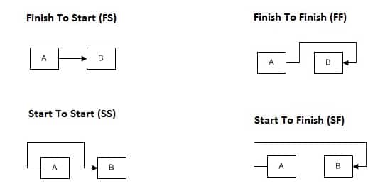
In Finish to Start dependency, the second activity cannot be started until the first activity completes. This is the most common type of dependency used in network diagrams. In Finish to Finish dependency, the second activity cannot be finished until the first activity finishes. In Start to Start dependency, the second activity cannot be started until the first activity starts. In the Start to Finish dependency, the second activity cannot be finished until the first activity starts.